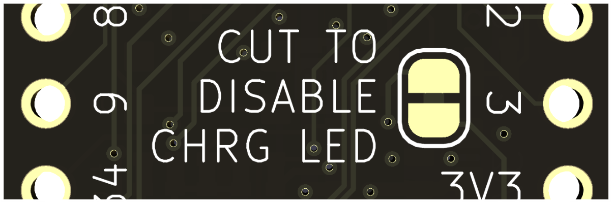
That is by design! The power and charge LEDs and corresponding resistors drain the battery, so they've been isolated to the 5V power domain so they will only light up and draw power when the board is either being powered by the USB connector, or by a 5V power source connected to the 5V header pin.
That is the correct behaviour! The charge IC can’t tell the difference between a full battery and no battery, so it cycles between trying to charge and not charge.
If you are not using a battery on your project, or you don't need the use of the charge status LED, you can disconnect it by cutting the jumper on the back of the board, as indicated, if that feature is on your board.
A strapping pin is a pin/IO that is used by the ESP32 during it's boot up cycle to set certain modes. IO0 for instance is used to select if the ESP32 boots into download mode, or if it boots running your user code.
You are not allowed to alter it with a pull-up/pulldown during boot, or it will not allow you to boot properly. You are only able to use that IO after your code is running.
For more information about strapping pins, please refer to the ESP32-S3 data-sheet on the Espressif website.
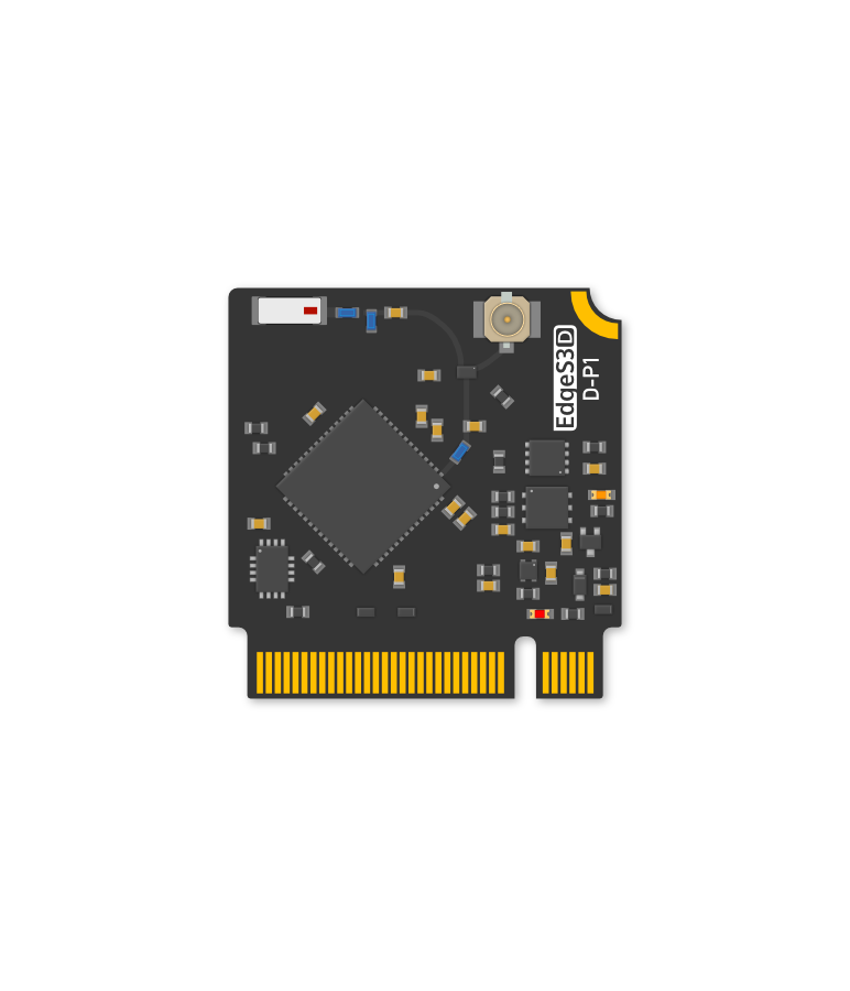
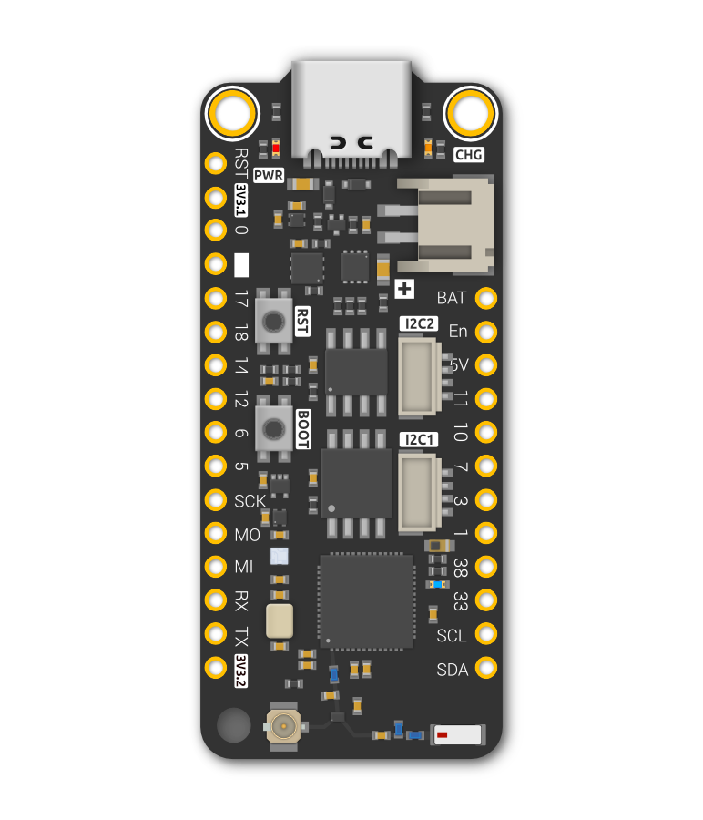
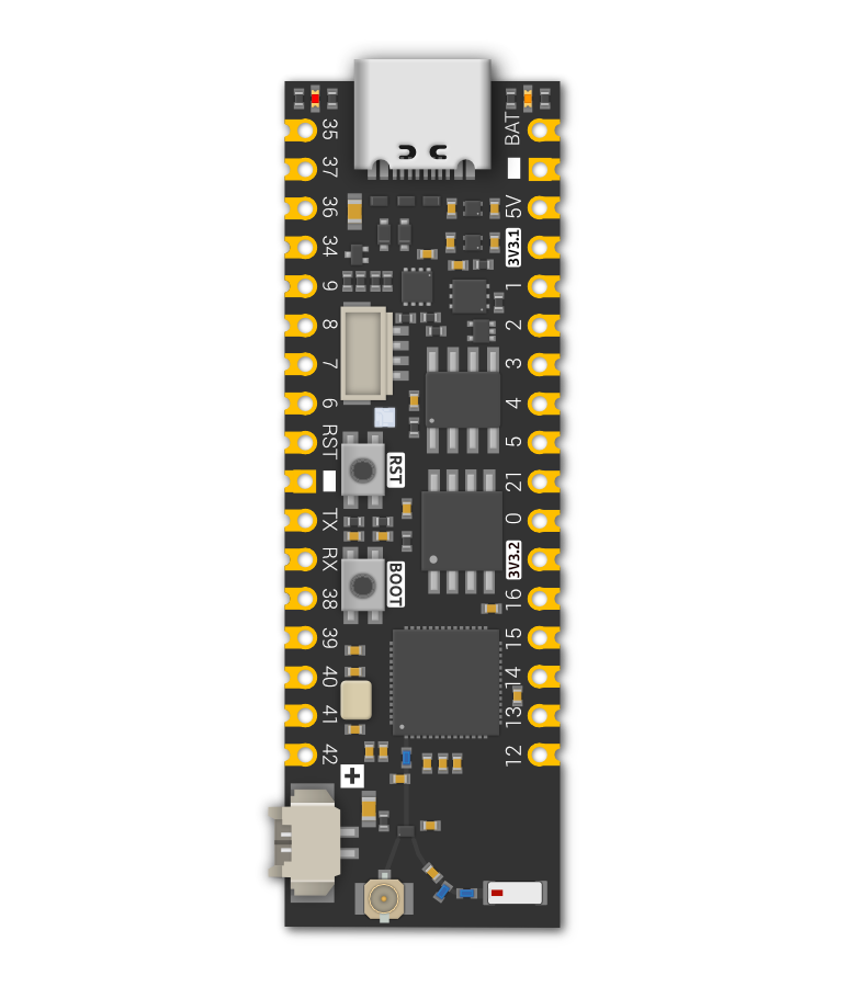
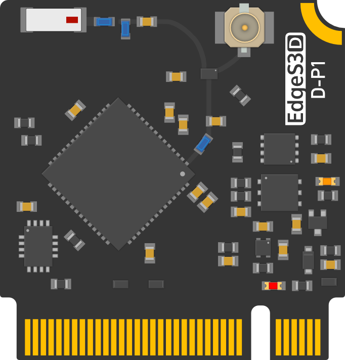
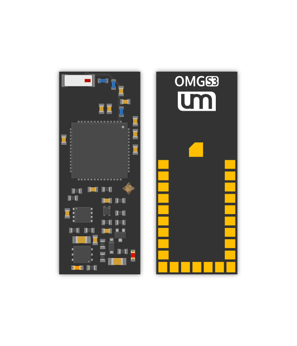
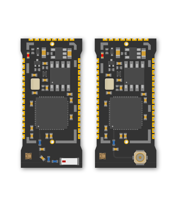
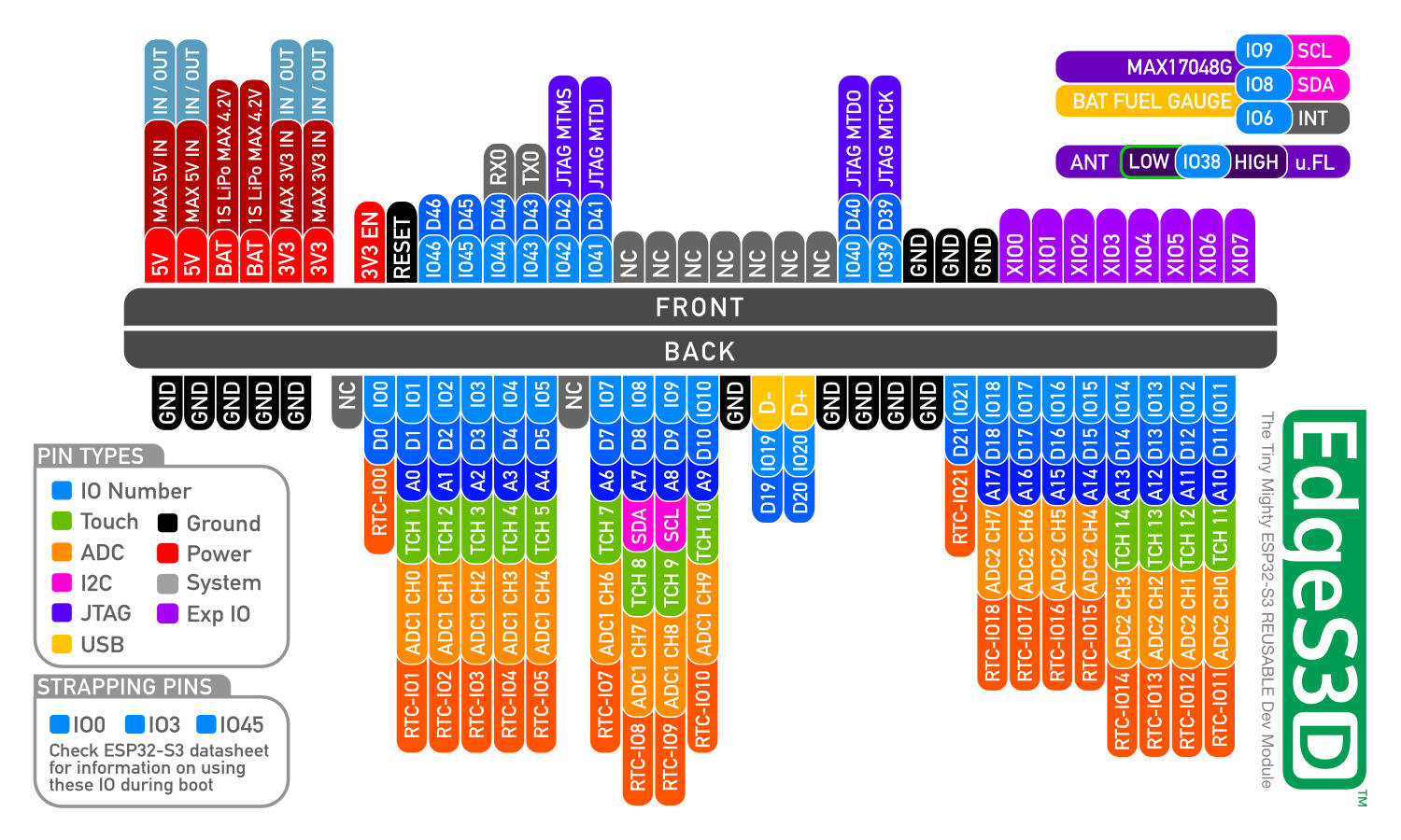
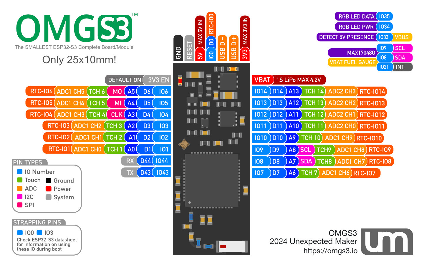
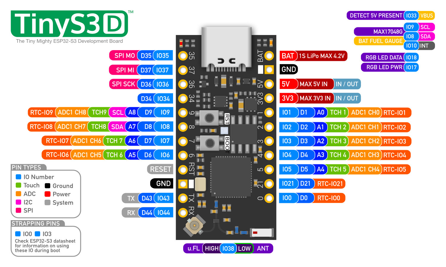
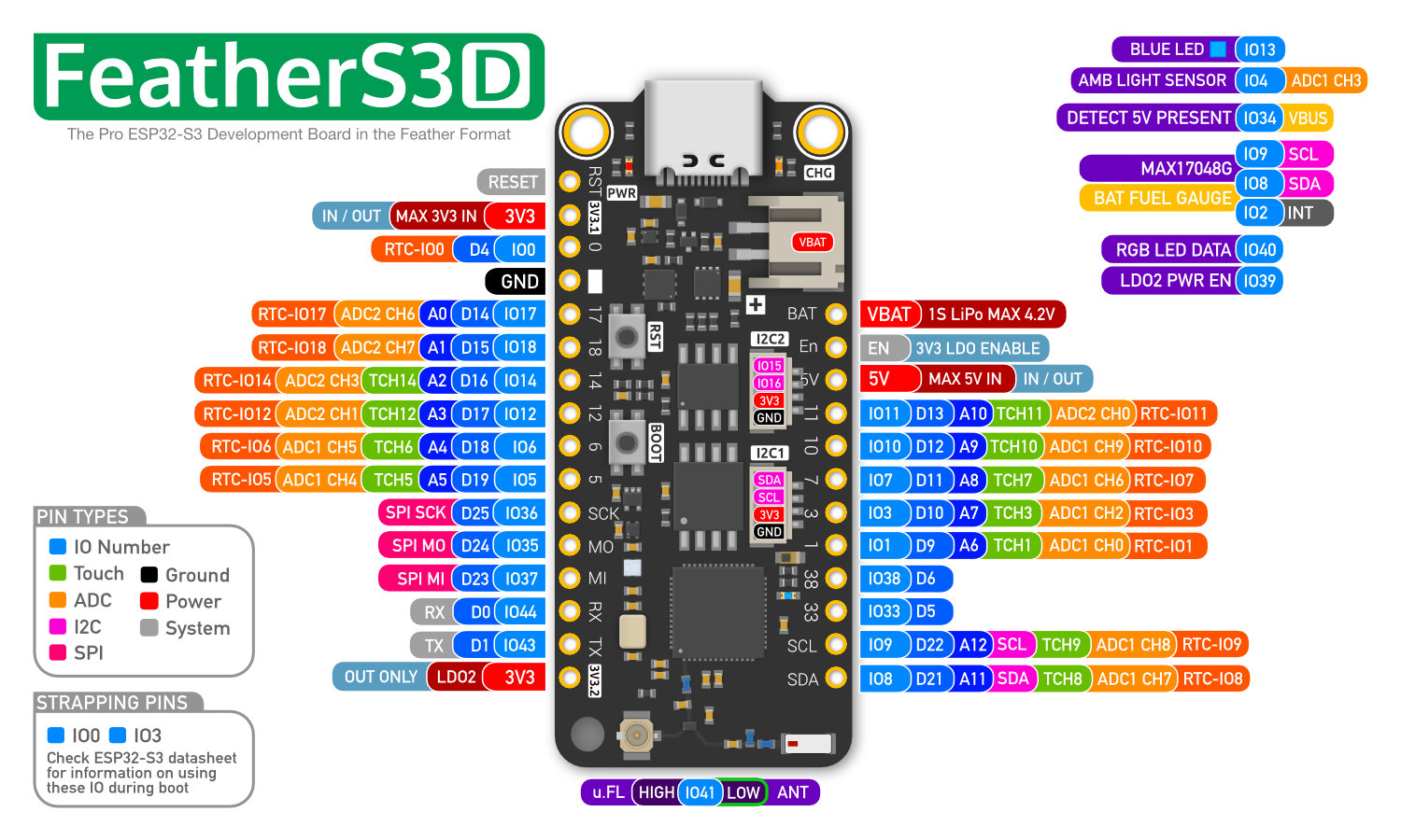
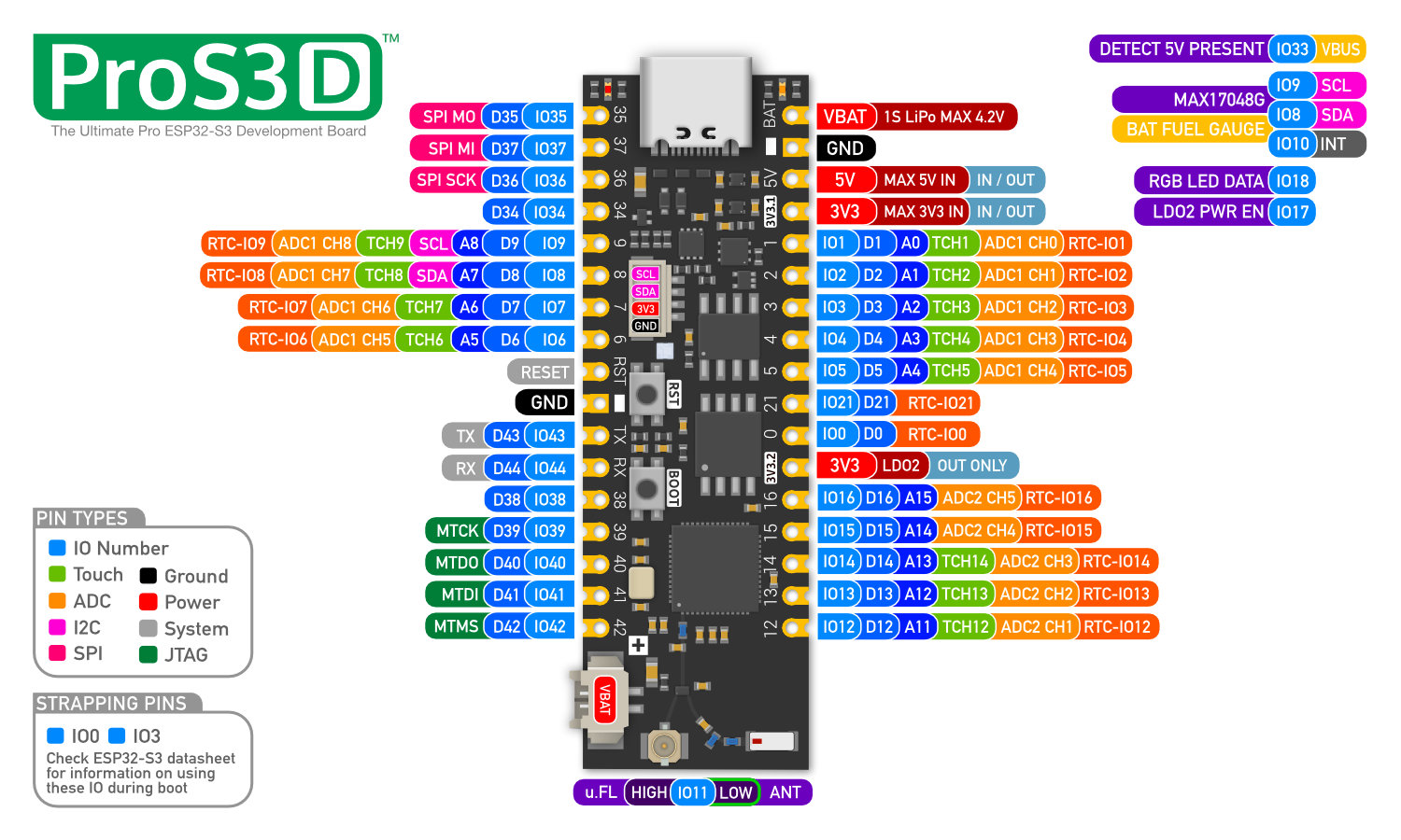
OMGS3, EdgeS3[D], TinyS3[D], FeatherS3[D] & ProS3[D] all have an I2C fuel gauge that you can query to get the current state of the bayttery.
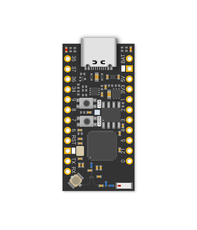
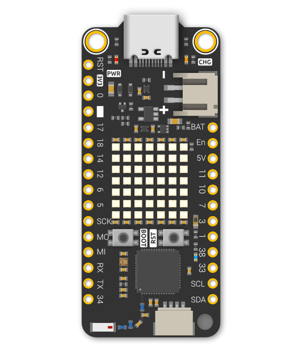
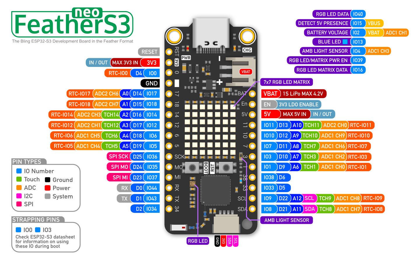
The FeatherS3 neo has the battery connected to an ADC pin that you can read to get an approximation of the voltage of the battery.
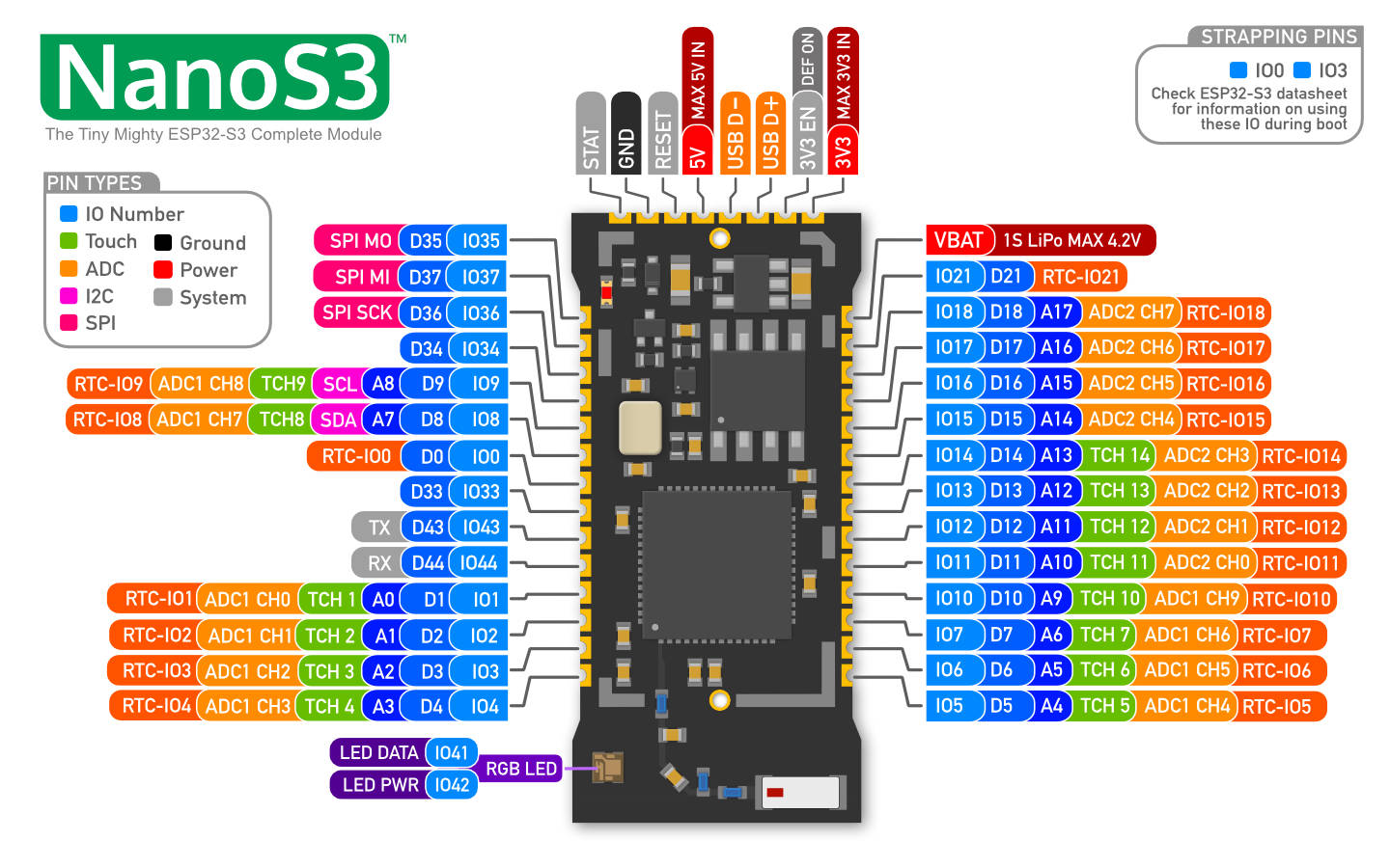
On the NanoS3, you have to add your own voltage divider to your carrier PCB to read the battery voltage, or you can also add a I2C fuel gauge if thats your preference.
Each of these indicated boards has an IO connected to a voltage divider on the 5V power rail that you can read to determine if there is a 5V power source connected or not. This allows you to alter your code based on the source powering your board in your project. Note: Check the helper library for your board for a function that lets you read the state.
On the NanoS3 & EdgeS3[D], you have to add your own voltage divider to your carrier PCB to check if the 5V source is present.
RX & TX are still connected to UART0, and still used with the USB when in CDC (download mode). Otherwise, you can use them as UART0 when connecting a module that uses serial, or use them as general IO, it's up to you.
The 5V pin on your board is an in and out pin. As an input, it will accept a voltage range between 4.8V and 5.2V. Please do not connect any power source over 5.2V to the 5V pin and please do not connect your battery to the 5V pin. It is for a 5V power source only.
When USB power is connected, you will get approximately 4.9V out of the 5V pin. The voltage drop is due to the reverse USB power diode that allows the USB and 5V pin to be power inputs at the same time, and prevents back feeding power into the USB.
The use case for having both connected is when you want to power your board from the 5V pin from an external 5V power source, but you also want to connect the USB to flash the board, or to get serial output.
If your board is being powered by any 5V source (USB or 5V pin) and a battery is connected to your board via the VBAT pin or connector, the battery will go into charge mode and the board will be powered via the 5V source.
Short answer? No. The 5V pin is for an external 5V supply input to the 5V power rail. The 5V rail has several additional connected components - such as the power LED - that will unnecessarily consume battery power.
Connect your battery to the VBAT pin or battery connector to minimise battery consumption.
Absolutely not! The 3V3 pin bypasses the onboard 3V3 LDO regulator, and if you connect a battery that can be as high as 4.2/4.3V, you could potentially damage components on the 3V3 rail that can't handle higher voltages than 3V3, including the ESP32-S3 chip itself.
This is really a tough question to answer as there are so many external factors that can affect WiFi & BLE radio performance, including the construction of the building you are in, your network layout, power or RF noise in your area and where you are placing your board.
All we can say is we spent a great deal of time tuning the matching network and the antenna implementation, to ensure it’s the best it can be. The rest is up to you and your environment.
To get your board into UF2 bootloader mode (assuming you have not stomped your shipping CircuitPython install with Arduino/IDF or MicroPython), follow these steps:
- Press the [RESET] button
- When the RGB LED is purple (if your board has one), press the [BOOT] button
You will then see the RGB LED on your board turn green once the filesystem is mounted.
On the NanoS3, OMGS3 and EdgeS3[D] you have to add your own buttons for [BOOT] (IO0) and [RESET] to your carrier PCB.
You can switch between each development environment, but each time you will need to put your board into download mode by holding [BOOT], clicking [RESET] and then releasing [BOOT] and then flashing the respective firmware you require onto the board.
It's also good practice to erase your flash before you switch environments/languages to ensure the new filesystem partitions are setup correctly.
If you ever find you have gotten your board into a bad state with CircuitPython - Maybe you accidentally got it stuck in read-only mode or maybe it's stuck in a boot loop, you can put your board into safe mode which will boot the board, but not run any of the code. You can then fix your issue and reset the board.
To get into safe mode, follow these steps:
- 1. Press the [RESET] button to reset the ESP32-S3 chip
- 2. After the RGB LED has gone purple and then off, press and hold the [BOOT] button for a few seconds
Your board should now be in safe mode.
The 5V pin can only produce 5V if there is a 5V source connected to the board via the USB connector. There is no boost/step-up converter on these boards to provide 5V from the VBAT input.
If you want to run off battery and require a 5V supply for an external module or sensor, you'll need to provide your own external boost converter. Something like the 5V Step-Up/Step-Down Voltage Regulator S7V7F5 from Pololu.
That's correct! LDO 2 is tied to both an IO and VDD for the Flash/PSRAM, so when the ESP32-S3 goes into deep sleep, it automatically shuts down LDO 2 for you, so you don't have to remember to do it yourself.
On the ProS3[D] and FeatherS3[D], the RGB LED is powered via LDO2, so you need to enabled LDO2 before you'll see output on the LED.
On the TinyS3[D], OMGS3 and NanoS3, the RGB LED is powered via an IO pin, so you need to set that to high before you'll see output on the LED.
Check the included pinout cards to find which IO you need to set for your specific board.
These boards includes everything you need other than a USB connector and buttons for IO0 and RESET. Depending on the design, some projects don't need a USB connector, or boot option buttons, so those need to be provided by you, if required.
Though it is possible to hand solder a NanoS3 to a carrier board, you need to ensure the thermal pad on the back of the NanoS3 is electrically connected to your GND, so that also requires soldering. Please check out the provided NanoS3 Carrier PCB design (KiCAD 7) for an example of a design that can be hand soldered.